
|
Lost Tech Archive |
An Overview of Integral MicroOptics
Introduction
Integral MicroOptics (IMO) is a new approach to encoding, processing, and displaying images. It can be applied to create a wide range of thin, lightweight, and sophisticated image processing and data storage/retrieval devices. These devices can be manufactured with inexpensive techniques and materials. Further, many of these systems are usable under ordinary ambient lighting and are immune to electromagnetic interference as well as stress and vibration.
This paper first defines IMO as an optical processing technology designed to manipulate images composed of points dynamically generated by separate parallel optical systems. Secondly, this paper proposes a practical implementation of this technique with a material where all components can be simultaneously manufactured in sheet form in a single manufacturing step. Thirdly, this paper will examine some of the possible applications of this technology.
Background
Traditional optical systems consist of components that operate serially on an entire image. Since each element deals with the complete image, these elements must be carefully designed and built to compensate for distortions and aberrations that inevitably arise when a single element must handle an entire image by itself. This situation is analogous to the state of electronics in the 1950's. Systems were built by connecting individual active components with wires in boxes custom made for each application. This approach puts a limit on the complexity of any design - 6 transistor radios, 5 tube radios, 20 tube TV's were about as complex as mass produced items could be using this approach. Pocket calculators, digital wristwatches, and portable computers were unthinkable with this technology. Likewise, today, most optical systems have few components - a consumer telescope maybe 6, a high end microscope may have 30. The components are few and large, and the interconnect distances are large.
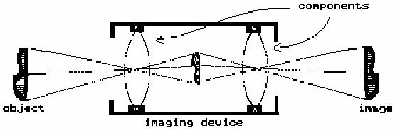
The transition from discrete electronic components to integrated circuits came from the ability to miniaturize components and manufacture many of them functionally connected at the same time. IMO systems consist of successive planes of arrays of miniature optical elements where each element is optimized to produce only a single point, or pixel, of the resulting image. The resulting image, then, is a composite, or integral image made up of typically several hundred thousand component points each individually generated by a separate serial optical processing stream.
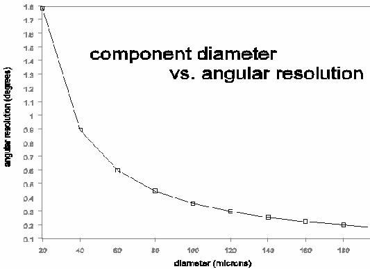
Traditionally, because of the techniques available and hence the size scale involved, it has been far simpler to design and manufacture imaging devices based on a serial arrangement of lensing components working on an image rather than a collection of components processing values of pixels in parallel. This preference has hidden the potential of IMO. Practical IMO systems use serial sets of components to generate only a point, or pixel, of the final image. To produce images of a quality comparable to existing imaging systems requires a density of elements - and hence an element size - that cannot be achieved using traditional techniques. The literature on Integral Photography (an early example of an IMO application) repeatedly refers to this problem of making elements of small enough size to achieve packing densities sufficient for high quality image production.
The situation is similar to having enough dots per inch in a halftone image to produce an image where the dots do not intrude on the perception of the image as a whole. In the case of IMO systems, however, each dot is an entire active subsystem. Limits on lens diameters have, in the past, precluded the small sizes needed for acceptable pixel densities for IMO planes. Furthermore, designing and manufacturing such systems is far more complex than the large curves and straight-forward layout of traditional optical imaging systems.
These severe limitations on the implementation of this technology have restricted its use to various relatively coarse 3 dimensional displays such as stereo panoramagrams and integral photography and in the well known novelty items employing lenticular screens that change between two or several images as the viewing angle is changed. All of these use arrays of simple refractive components. In particular, this limitation on implementation has hidden investigation into this technology as a general approach to imaging devices.
Fundamental Concepts
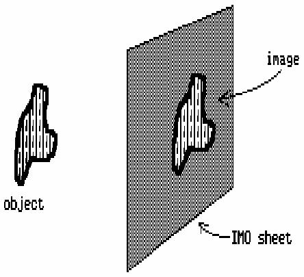
IMO systems are image computers. The output of an IMO system is an image.
Rather than working with an image as a whole, IMO systems, like bitmapped computer graphic devices, treat images as an array of points. The shading of each point, called a pixel, depends on the viewing angle.
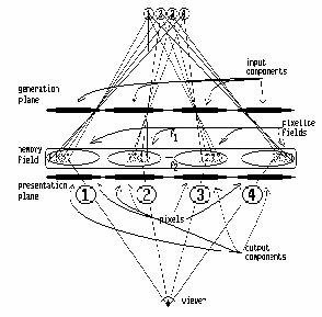
An IMO system that acquires, processes, stores, and displays images is comprised of three main subsystems: the generation plane, the resource plane, and the presentation plane arranged as shown below.
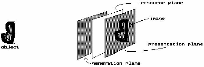
Major IMO Sub-Systems
Figure 3
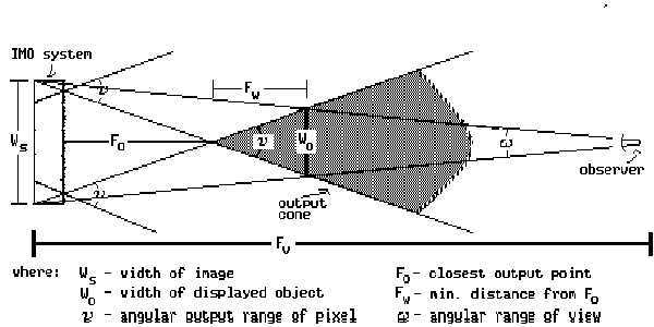
The function of each subsystem is:
The presentation plane - the array of components that present pixelated images to the viewer with pixel intensities dependent on the angle of view.
The resource plane - the array of components which make available encoded shading information in a form usable by the presentation plane.
The generation plane - the array of components that inputs and encodes image data onto a usable resource plane format.
An examination of the processing of a single pixel through an IMO system illustrates the functioning of the system.
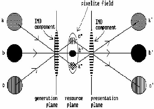
Angular shading information (labeled a,b,c in figure 4 above) at a component on the generation plane is transformed into spatial shading information (labeled a",b",c" in figure 4) in the pixelite field on the resource plane by the IMO component on the generation plane.
The resource plane is a planar mapping of angular shadings used by the presentation plane. Each component on the presentation plane has a corresponding area on the resource plane called the pixelite field which supplies it with shading information for all angles that it services. There is a discrete area in the pixelite field for every output angle of the component on the presentation plane. The pixelite fields may be generated live, can be pre-recorded, or can be some combination of the two.
Spatial shading information from the pixelite field on the resource plane is transformed into angular shading information (labeled a',b',c' in figure 4 above) by the component on the presentation plane. Since images are composed of points, each pixel need present only one shading value for any one viewing angle. If we think of the IMO component on the presentation plane as a hole in an opaque sheet and the pixelites (a",b",c") on the resource plane as three different shadings behind it, then a viewer at a' would see the shading a" through the hole (the IMO component), while a viewer at b' would see the shading b", and c' would see c".
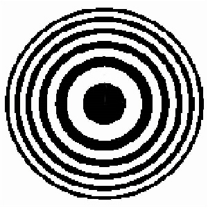 Unfortunately,
small holes are not sufficient to produce acceptable imagery. A larger
pixel surface area and greater angular resolution are needed. Fresnel
Zone Plates are flat components based on diffraction that will
transform angular shading information in one plane into spatial shading
information on another plane. That is basically the same effect that a
lens produces when it focuses an image. The use of zone plates for
focusing a light image dates back at least to Fresnel's presentation of
the effect before a prize committee of the French Academy in 1818 and
there are references to the effect at least a century earlier. Zone
plates become simpler as their size decreases, their internal component
geometries being determined by the wavelengths of the light involved.
Additionally, the focal lengths of zone plates become very short as
their size decreases allowing for short distances between serial
components.
Unfortunately,
small holes are not sufficient to produce acceptable imagery. A larger
pixel surface area and greater angular resolution are needed. Fresnel
Zone Plates are flat components based on diffraction that will
transform angular shading information in one plane into spatial shading
information on another plane. That is basically the same effect that a
lens produces when it focuses an image. The use of zone plates for
focusing a light image dates back at least to Fresnel's presentation of
the effect before a prize committee of the French Academy in 1818 and
there are references to the effect at least a century earlier. Zone
plates become simpler as their size decreases, their internal component
geometries being determined by the wavelengths of the light involved.
Additionally, the focal lengths of zone plates become very short as
their size decreases allowing for short distances between serial
components.
Fresnel zone plates should not be confused with Fresnel lenses (see Fresnel Lenses and Zone Plates.)
{ discuss difference between amplitude and phase modulating zone plates }
{ discuss Gabor zone plates }
Varying density by embossing a surface with the rings significantly increases the brightness transmitted by a component by shifting the phase of light components instead of blocking them. Being essentially a planar object as opposed to large curved surfaces, practical element densities up to several hundred elements per linear inch can be manufactured using available printing and embossing processes.
Additional improvements in brightness and resolution can be achieved by overlapping the zone plates slightly so that some of the outer rings share the same area on the screen. It is important to note that the bands are wave phase adjustment patterns and the overlapping areas are comprised of recorded wave phase adjustment patterns and not just an overlapping set of rings.
Chromatic aberration becomes a significant issue at the sizes of components needed and there are several ways of taking advantage of the effect. The simplest is to have separate resource planes for each color. This lends itself well to photographic applications which already use separate emulsions stacked on each other for separate colors. Another approach, extensively used in the graphics arts and video industries, is to restrict each pixel to a single color and use groupings of pixels much like the RGB triads used in color CRT's or color separations done in halftone printing. A third approach would make use of color corrected zone plates. In this approach, separate zone plates are designed to focus separate colors on the same resource plane. These zones plates are designed also as filters and they are superimposed on the same center such that different wavelengths interact with different components at the same location resulting in all colors focusing at the same plane. This would be similar to the subtractive color processes used in modern color transparency films.
Diffraction grating elements can be used if separation of wavelengths or color is specifically desired. In this case, the pixelite fields have mappings of color separations that are used by the presentation plane. This allows construction of images containing calibrated spectral graphs. Likewise, variations (derived by numerically generating a phase shifing or absorbing surface that performs the desired transform function) can be easily incorporated into portions of the image.
{ Discuss off axis zone plates and other variations as specific instances of cuts through the wave pattern in space.}
Aliasing of sampled data is generally considered a problem by engineers. IMO systems rely on this phenomenon to create a large image out of a multitude of related small sample sets. In general, IMO systems use the generation plane to create a resource plane consisting of a multitude of pixelite fields that are the sample sets for the presentation plane. The presentation plane selects samples from this multitude of repeating images at a spatial frequency almost equal to the component spacing of the generation plane but increasing slightly as one moves off center. This results in a set of points selected by the viewer that recreates a geometrically accurate reconstruction of a single large image incorporating any transform designed into the system. By careful selection and placement of the components and relative geometries of the three planes, sample sets can be made available to the presentation plane allowing the generation of enlarged images of small areas, reduced images of large areas, superpositioning of prerecorded data with live images, spatial filtering, spectroscopic analysis, and many other applications.
Limitations
{limits of wavelength}
{limits of current manufacture skill}
{limits of viewing capability}
Realization
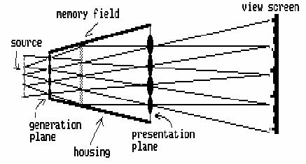
Practical IMO Systems consist of at least a resource plane and one other plane and may have more as well as other components depending on the application. The general principles can be seen if we examine a simplistic example of this technology.
In figure 6 above, there is a generation plane and presentation plane of four components each separated by some space with an object on one side and a viewer on the other. The four components of the generation plane each generate an image of the object in their corresponding pixelite fields. The components of the presentation plane are on the same centers as the generation plane components but the focal length of the components is shorter so that the distance from the pixelite field images to the presentation plane is shorter. The viewer sees a composite image composed of a set of points, or pixels, selected one from each pixelite field by each component of the presentation plane. Because of the difference in focal lengths of the two screens, the image is composed of pixels from a small area of the sampled object. By careful selection of the geometry of the screens, the apparent image as seen by the viewer is composed of a set of points that covers the entire field of view in a geometrically accurate manner. Thus, the system acts as a magnifier with the added advantage that full parallax and stereopsis is maintained throughout the field of view designed into the system. The reverse geometry would result in a wide angle viewer.
A practical device using this approach requires at least thirty and more likely one to three hundred components per linear inch to produce high quality images. To maintain separation of pixelite fields at that density, focal lengths of components must be in the 100 to 1000 micron range. If the generation and presentation plane components are made on the two sides of a sheet of transparent material, the resource plane images can be generated within the material and image magnifiers can be manufactured on a single continuous sheet.
Screen Design
Screens can be designed to have particular characteristics. Software has been created that will generate a description of a screen and component geometries allowing interactive changing of viewing distance, media thickness, size, refractive index, zone center diameter, pixels/inch, field of view, pixel spacing, and wavelength selection as well as variations on plotting devices. A more general approach, also implemented in software, involves calculating a raster image of a phase absorbing plane that performs the required transform. This data, derived by either method, is then plotted at the required size and manufactured in the desired transparent media. These sheets, called MicroOptic Sheetstm, built with standardized centers and thicknesses based on focal lengths, can then be stacked to create a multitude of imaging devices.
The following relationships are useful in designing IMO systems:
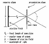
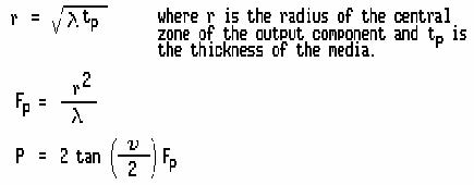
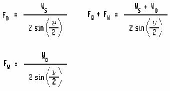
For example, assuming light with a wavelength of 0.51 microns, a system for volumetric image reconstruction designed for viewing from at least 15 inches with a 30 degree angular viewing range could have the following geometry: A sheet of transparent material 20 inches square and 6 mils thick having a refractive index of 1.496 with the presentation plane embossed on one side and a photographic emulsion on the other side would have the pixel centers in triads with 82 micron separation between component centers. This would result in 312 pixels per linear inch. The components would be zone plates with a center zone diameter of 14.4 microns. The components would have 29 zones resulting in a component diameter of 77.53 microns.
Development Activities
Three phases of development have taken place to date. The first involved selecting potential approaches to implementing crude prototypes. A photographic approach was selected as the media of choice to produce images that could be used as screens and as a storage media for resource planes. Stored resource plane systems were selected for development because a single screen could be used for both the generation plane and the resource plane eliminating potential alignment and repeatability problems.
Early work was focused on creating a workable screen and many attempts were done before the distinctions necessary for even a rudimentary prototype were known. This early work used simplified zone plates consisting of only the center zone because these could be generated using available equipment. Pixel density was also very coarse. Various means of generating components were tried including punching holes, cementing acrylic beads and using them as lenses, dot matrix printing, and manual photographic step and repeat. The first working image was made with a screen generated on a CRT and photographed on 4x5 film, duplicated, pasted up, reduced, duplicated, pasted up, reduced, and again duplicated, pasted up and reduced. The resulting screen had center zones that varied widely in diameter and roundness, but nevertheless produced a working image.
Most of the early work involved imaging objects at a distance of many feet from the screen. These attempts were very unsuccessful primarily because of the crudity of the components. Turnaround time on an experiment was long because of the time involved in handling and processing the many photographic steps in each try. This time lag was eliminated by copying the screen and using a translucent sheet as the resource plane. This made it possible to view the resulting image live.
The first working image was of a rectangle of plastic with two holes backlit by a square aperture behind it. The plastic was taped to a pencil and placed approximately one inch in front of the plate. It was from the many multiple images off to the sides that the need for careful spacing and separation of pixelite fields became obvious.
The software for generating screens was modified to take this into account and a new screen was created that allowed sufficient spacing between pixels. This screen was used in creating the 3D image of the clown and goose and a multiplex image consisting of 13 separate images of arrows indicating the direction to move to find a plus sign image straight on. These screens had 9.6 pixels per linear inch and, because they only had the center zones, required bright illumination from behind. As can be seen from the photomicrographs, these center zones were far from round and varied from -10% to +500% of the desired diameters. Nevertheless, the resulting images are clearly recognizable and the dynamics of the system clearly function.
The need for greater brightness, greater pixel density, and greater resolution was obvious and a method for creating a new screen was investigated. Holographic and other optical methods were looked into and ultimately dropped because of lack of access to equipment as well as lack of versatility of design. A software approach to generating data that described components and systems was adopted and the existing design software was modified to generate image data files for the Matrix QCR video output camera. Because the plotting dot size, spacing, and frame size of the output of the camera were not at the level needed for the screens, a means of doing step and repeat as well as photo-reductions was sought. After many attempts in-house as well as at several graphic arts houses and printer houses, this approach was shelved to pursue generating a screen at the semiconductor fabrication facility at the University of Wisconsin. A screen was designed and built that would use the glass plate substrate as a focusing medium. Because of the thickness of the plate (90 mils), the pixel density was only at 25 pixels per linear inch, but because of the detail possible (1 micron lines), the zone plate components had over 150 rings which significantly increased the possible brightness and resolution.
The handling of objects with that level of small detail required construction of a clean room environment and special jigs and fixtures for handling, alignment, and exposure as well as new techniques and equipment for analyses of experiments. Early work with this screen was very disappointing because of the lack of control over exposure, processing, and alignment. A course of study was undertaken to learn the dynamics of using this type of imagery.
{discuss current findings and efforts}
Applications
We have examined how a sheet magnifier can be built. This magnifier would be useful in medical applications not only for its optical properties but also as a spatter shield. Another application would be as a video screen magnifier, especially if the MicroOptic Sheets were designed to produce an interpolated image between the lines of the standard video signal, thus apparently doubling the resolution of standard video.
A slightly different configuration results in a MicroOptic projection lens. Each pixel in the system projects a single pixel on the screen. Figure 9 illustrates the arrangement required.
Note that the centers of the generation plane, the memory field, and the presentation plane are in line with the angle of enlargement, not purpendicular to the planes of the system. This is an application where specific presentation output angles are designed into the system to accomodate specific output requirements.
The pixels on CRT's and flat panel displays can be used to create the pixelites in a resource plane. With the appropriate presentation plane in place, live volumetric imaging of computer and video data becomes available.
If a light sensitized emulsion is placed at the resource plane, the image recorded, and then viewed through the presentation plane, a 3 dimensional image of the object is reconstructed for the viewer that demonstrates full parallax as the angle of view is changed. This, in fact, is what happens in integral photography using fly's eye lenses. IMO implementation would provide a quality hitherto not possible to this type of 3D imaging. From a manufacturing standpoint, the film could be made by taking a transparent sheet stock, printing or embossing the IMO pattern on one side, and coating the other with a light sensitive emulsion. With appropriate screens manufactured as part of photographic film, high quality 3D film can be manufactured for use in many applications not amenable to holographic techniques such as X-ray images, furnaces, plasmas, large displays, and portraits. Normally the generation and presentation planes would have the same focal lengths and since only one is used at a time, this allows the same screen to be used for both. However, if different focal length screens were used for recording and viewing, a magnified or wide angle image would result.
With suitable framing, windows with recorded views could be made. Along those same lines, floor tiles could be made with repeating patterns such as grass, water, (or hot coals or an aerial view!). Likewise, ceiling panels with sky, clouds, or whatever would add an openness to a room not possible with other building materials.
Each angle of view actually selects a separate image which does not have to be related to any other image. Many pages of print and graphics can be multiplexed onto a single IMO sheet and each page selected by viewing angle. Such devices could be made either to show an image by itself, or by leaving the material transparent, to superimpose an image onto a scene viewed through it. It would be practical to manufacture such devices by printing the multiplexed pattern on one side and embossing the screen on the other. Applications would include information retrieval systems (both directly viewable or projectable microfiche type sheets or in a format suitable for computer data storage), and displays that project pointers into space and display some measurement such as digital optical rangefinders or dashboard displays that can point out objects or areas forward of the vehicle. An interesting variation is the use of an elastic screen material programmed with a menu when viewed flat, but displaying images appropriate to the menu items selected by pushing on the item by a user.
Animation sequences can be created that are viewed by turning the sheet. A multiplexed image sheet can consist of a set of frames from an animation sequence. Applications would include advertising displays, signage, and perhaps animated highway displays, such as moving arrows that rely on viewer motion to sequence a set of images.
Spatial filters can also be implemented using this technique. A screen that blocks out a spatial frequency component can be incorporated in the resource plane and the resulting apparent image will thus be modified. The resource plane would be comprised of the desired pattern repeated over the entire surface aligned with the centers of the pixels of the generation and presentation planes. Complex filtering of this type can produce a range of products that can recognize and accentuate shapes viewed through them.
If an IMO sheet has a mirror as the resource plane, the system will act as a high resolution autocollimating sheet with a prismatic effect. These would act as reflectors or as novelty mirrors or, if made as a tile, a dance floor that surrounds each object between the viewer and the screen in a rainbow of color.
Of course, combinations of these applications could also be created that would lend themselves to specific applications such as magnifiers with data displays and shape recognizers built in.
Conclusions
We have examined the foundations of Integral MicroOptics as well as some of the reasons why it has not been available. Implementation is straightforward using available techniques. Magnifiers, viewers, 3D recording and playback of images and data, and optical processing devices can be built using the techniques described that have advantages over other methods. This technology has many parallels to the semiconductor industry, but is simpler in execution while at the same time as rich in applications. Many variations are possible and speculation can best be understood in the context of someone looking at the future of electronics in 1958.
Bibliography
Optical Imaging System Using Tone-Plate Elements , US patent 4,878,735 Ivars Vilums. Filed Jan. 15, 1988, Ser. No. 144,942 Int. Cl. G02B 27/22, 27/44. U.S. Cl.350--131. 52 claims.
Optical Properties of a Lippmann Lenticulated Sheet, Herbert E. Ives, Bell Telephone Laboratories N.Y., Journal of the Optical Society of America. vol. 21, March, 1931, pages 171-176.
Synthesis of Fresnel Diffraction Patterns by Overlapping Zone Plates, R.L. Conger, L.T. Long, and J.A. Parks, Naval Weapons Center, Corona, California, Applied Optics, Vol. 7, No. 4, April, 1968, pages 623-624.
The Amateur Scientist: The Pleasures of the Pinhole Camera and its Relative the Pinspeck Camera, Jearl Walker, Scientific American,
Optimum Parameters and Resolution Limitation of Integral Photography, C.B. Burckhardt, Bell Telephone Laboratories, Inc., Murray Hill, N.J., Journal of the Optical Society of America, vol. 58, no. 1, January, 1968, pages 71-76.
Formation and Inversion of Pseudoscopic Images, C.B.Burckhardt, R.J. Collier, and E.T. Doherty, Bell Telephone Laboratories, Inc., Murray Hill, N.J., Applied Optics, vol. 7, no. 3, April, 1968, pages 627-631.
The Effect of Semiconductor Processing Upon the Focusing Properties of Fresnel Zone Plates Used As Alignment Targets, J.M. Lavine, M.T. Mason, D.R. Beaulieu, GCA Corporation, IC Systems Group, Bedford, MA., Internal Document.
Obtaining a Portrait of a Person by the Integral Photography Method, Yu. A. Dudnikov, B.K. Rozhkov, E.N. Antipova, Soviet Journal of Optical Technology, vol. 47, no. 9, September, 1980, pages 562-563.
Holography and Other 3D Techniques: Actual Developments and Impact on Business, Jean-Louis Tribillon, Research and Development, Holo-Laser, Paris, France, Conference Title: ThreeDimensional Imaging. Conference Location: Geneva, Switz. Conference Date: 1983 Apr 2122, Sponsor: SPIE, Bellingham, Wash, USA; Assoc Natl de la Recherche Technique, Paris, Fr; Assoc Elettrotecnica ed Elettronica Italiana, Milan, Italy; BattelleGeneva Research Cent, Geneva, Switz; Comite Francais d'Optique, Fr; et al. Source: Proceedings of SPIE The International Society for Optical Engineering v 402. Publ by SPIE, Bellingham, Wash, USA p 1318 1983 CODEN: PSISDG ISSN: 0277786X ISBN: 0892524375 E.I. Conference No.: 04122
An Analysis of 3-D Display Strategies, Thomas F. Budinger, Dept. of Electrical Engineering & Computer Sciences and Donner Laboratory, University of California, Berkeley, Ca., SPIE vol 507, Processing and Display of Three-Dimensional Data II (1984), pages 2-8.
Space Bandwidth Requirements for Three-Dimensional Imagery, E.N. Leith, University of Michigan, Ann Arbor, MI., Applied Optics, vol. 10, no. 11, November, 1971, pages 2419-2422.
Holography and Integral Photography, Robert J. Collier, Bell Telephone Laboratories, Physics Today, July, 1968, pages 54-63.
Two Modes of Operation of a Lens Array for Obtaining Integral Photography, N.K. Ignat'ev, Soviet Journal of Optical Technology, vol. 50, no. 1, January, 1983, pages 6-8.
Limiting Capabilities of Photographing Various Subjects by the Integral Photography Method, Yu. A. Dudnikov and B.K. Rozhkov, Soviet Journal of Optical Technology, vol. 46, no. 12, December, 1979, pages 736-738.
Wide-Angle Integral Photography - The Integram (tm) System, Roger L. de Montebello, SPIE, vol. 120, Three-Dimensional Imaging(1977), pages 73-91.
Through a Lenslet Brightly: Integral Photography, Scientific American, vol. 219, September, 1968, page 91.
The Applications of Holography, Henry John Caulfield (Sperry Rand Research Center, Sudbury, MA) and Sun Lu (Texas Instruments, Inc., Dallas, Tx.), Wiley Series in Pure and Applied Optics, 1970, Library of Congress Catalogue Card Number: 77-107585, SBN 471 14080 5
copyright 1986 by Ivars Vilums. All rights reserved.